A 1.1.5 The fetch, decode and execute cycle
A 1.1.5 Describe the fetch, decode and execute cycle.
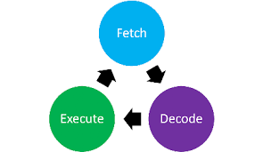
Every program reaches the CPU as a sequence of machine language instructions, and the CPU handles each one in exactly the same way: it fetches the instruction from memory, decodes it to work out what is required, then executes it. This loop repeats millions of times a second for as long as the program runs, which is why it is sometimes called the heartbeat of the processor. The cycle depends on a small set of registers inside the CPU and on the three buses that connect the CPU to main memory. This page describes what happens at each of the three stages, then explains how the address, data and control buses carry information between memory and the registers throughout the cycle.
Last Updated: 18 July 2026
Key Questions
- What happens at each stage of the fetch, decode and execute cycle?
- Which registers does the cycle use, and what does each one hold?
- How do the address, data and control buses connect the CPU and memory during the cycle?
IB Command Term note
Describe means give a detailed account. For this topic, a describe question expects the three stages in the correct order, with the registers and buses named at the points where they act. Listing the stage names alone is an outline, not a description. To describe the fetch stage you must say what moves where: the address in the PC is copied to the MAR, the instruction travels along the data bus into the MDR, and so on.
What is the fetch, decode and execute cycle?
The fetch, decode and execute cycle is the process every CPU uses to carry out the instructions of a program. The CPU fetches the next instruction from main memory, decodes it so the Control Unit knows which operation is required, and executes it using the ALU and registers. The moment one instruction completes, the cycle begins again with the next, and this continues until the program ends.

The registers the cycle depends on
A register is a small, very fast storage location inside the CPU. Four registers do most of the work in this cycle, and their names tell you what they hold.
| Register | What it holds |
| Program Counter (PC) | The memory address of the next instruction to fetch |
| Memory Address Register (MAR) | The address of the memory location about to be accessed |
| Memory Data Register (MDR) | The data or instruction just read from memory, or about to be written to it |
| Instruction Register (IR) | The current instruction, held while it is decoded and executed |
Stage 1: Fetch
The fetch stage moves the next instruction from main memory into the CPU. It follows the same fixed sequence every time:
- The address held in the PC is copied into the MAR.
- The address travels along the address bus to main memory, while the Control Unit sends a read signal along the control bus.
- Memory returns the instruction stored at that address along the data bus, and it is placed in the MDR.
- The instruction is copied from the MDR into the IR.
- The PC is incremented so that it points at the following instruction, ready for the next cycle.
Notice that the PC is updated during the fetch, not at the end of the cycle. By the time the current instruction is being decoded, the CPU already knows where the next one lives.
COMMON EXAM MISTAKE
Students routinely swap the MAR and the MDR. The names tell you which is which: the Memory Address Register holds an address (where to look), and the Memory Data Register holds data (what was found there). An answer that sends the instruction to the MAR, or the address to the MDR, describes a cycle that cannot work, and the fetch-stage marks depend on getting this right.
Stage 2: Decode
Decoding happens entirely inside the CPU. The Control Unit examines the instruction now sitting in the IR. A machine language instruction has two parts: the opcode, which specifies the operation to perform, and any operands, which are the data or addresses the operation will use. By separating these, the Control Unit works out which components, such as the ALU or a particular register, the execute stage will need.
Stage 3: Execute
The Control Unit now sends signals along the control bus to activate the components the instruction requires. If the instruction involves arithmetic or logic, the ALU performs the calculation on values moved in from registers. The result is stored back in a register, such as the accumulator, or written to main memory, in which case the address goes out on the address bus, the data goes out on the data bus, and a write signal goes out on the control bus. With the instruction complete, the cycle returns to the fetch stage.
How do the three buses connect the CPU and memory?
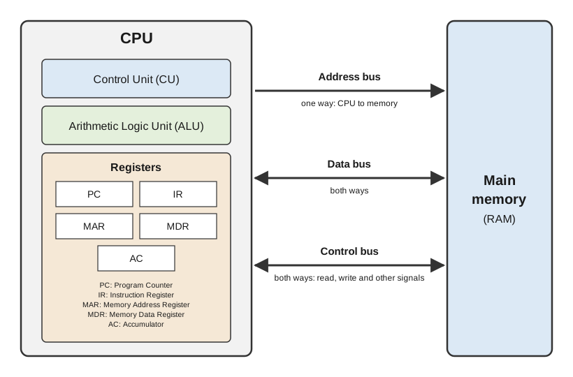
A bus is a set of parallel wires carrying information between components. The cycle uses three, and each has a single, distinct job. Keeping their roles separate matters because exam questions on this topic usually ask which bus carries what, and in which direction.
| Bus | What it carries | Direction | Role in the cycle |
|---|---|---|---|
| Address bus | Memory addresses, sent from the MAR to memory | One way: CPU to memory | Fetch: carries the address of the next instruction. Execute: carries the address of any data to be read or written |
| Data bus | Instructions and data | Both ways | Fetch: carries the instruction from memory to the MDR. Execute: carries data between memory and the registers |
| Control bus | Control signals such as read and write | Both ways | Coordinates every stage: a read signal triggers the fetch, and further signals activate components during execution |
The direction of the address bus is worth a second look. Only the CPU ever asks for a memory location, so addresses flow one way. Data, by contrast, is sometimes read and sometimes written, so the data bus must work in both directions.
One instruction from start to finish
The three stages are easiest to hold together by following a single instruction through a complete pass.
WORKED EXAMPLE
The instruction: add 5 to the value in register R1 and store the result in register R2.
Fetch. The address in the PC is copied to the MAR and sent along the address bus, with a read signal on the control bus. Memory returns the ADD instruction along the data bus into the MDR, it is copied into the IR, and the PC is incremented.
Decode. The Control Unit examines the instruction in the IR and identifies the opcode (ADD), the operand (5) and the registers involved (R1 and R2).
Execute. The Control Unit signals R1 to release its value and routes it, together with the value 5, into the ALU. The ALU performs the addition and the Control Unit stores the result in R2. The cycle then returns to the fetch stage for the next instruction.
Summary Reference
| Stage | What happens | Registers involved | Buses involved |
|---|---|---|---|
| Fetch | The next instruction is copied from main memory into the CPU and the PC is incremented | PC, MAR, MDR, IR | Address, data, control |
| Decode | The Control Unit interprets the opcode and operands of the instruction | IR | None: internal to the CPU |
| Execute | The instruction is carried out by the ALU and registers; the result is stored in a register or written to memory | General purpose registers, plus MAR and MDR if memory is accessed | Control, plus address and data if memory is accessed |
Try it on paper
Answer these in writing before checking the model answers. They use command terms the way the exam will.
1. Describe the role of the address bus and the data bus during the fetch stage. [2 marks]
2. Describe the steps the CPU performs during the fetch stage of the fetch, decode and execute cycle. [4 marks]
3. Outline what happens during the decode stage. [2 marks]
CPU simulator
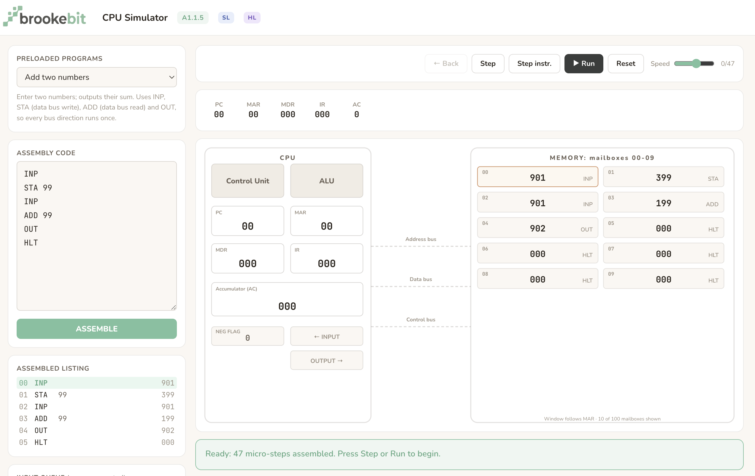
Follow the fetch-decode-execute cycle through on this simulator to see how the registers, buses, memory, control unit and ALU interact with simple programs.
A1.1.5 Quizlet.
Use the Quizlet to learn all the new key terms from this section. You can also choose different study modes to help you learn.
A 1.1.5 Quiz
What is the correct order of stages in the CPU cycle?
Which component of the CPU is responsible for decoding instructions?
What is the role of the Program Counter (PC) in the fetch-decode-execute cycle?
Which bus carries the memory address from the CPU to RAM during the fetch stage?
What happens during the execute stage of the cycle?
Which of the following is NOT a typical control signal sent on the control bus?
What is the role of the ALU in the fetch-decode-execute cycle?
How does pipelining improve CPU performance?
What is a common misconception about the fetch-decode-execute cycle?
Why is understanding the fetch-decode-execute cycle important?